Architecture Overview (Magic xpi 4.5)
Magic xpi 4.x consists of the following software components/elements:
-
In-Memory Data Grid (IMDG) – The in-memory data grid is middleware software composed of multiple server processes running on multiple machine instances (physical or virtual) that work together to store large amounts of data in memory, thereby achieving high performance, elastic scalability, and fail-safe redundancy.
-
Space – A Space is a data and business logic container (similar to a database instance) running in the data grid. A data grid can contain multiple Spaces. Magic xpi 4.5 uses two main Spaces, and a third Space for mirroring to the database, for running multiple projects. For redundancy and scalability, data and business logic in the Spaces are replicated and partitioned across all machines participating in the data grid, ensuring continuous service even in case of machine or software failure.
-
Magic Processing Unit (PU) – The Magic PU is a software module that runs in the Space and performs various management tasks on the project objects. This PU monitors and manages all Magic xpi objects and makes sure the server is running properly. The Magic PU has a number of functions, including:
-
-
Identifying flow timeout situations and recovering from them
-
Identifying hung/crashed workers and servers and recovering from them
-
Distributing management messages to running servers
-
Clearing completed flow requests
-
Gathering statistics on project entities
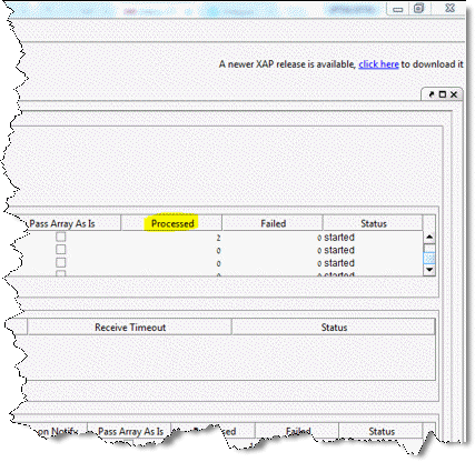
The various PUs can be seen in the GigaSpaces UI, under Event Containers. There is additional information in the GigaSpaces UI which can be useful. For example, the Processed column provides details about the number of requests that were processed in each PU, and how many timeouts occurred, and so on, as shown below.
|

|

|
-
Magic xpi Server – The Magic xpi server is an Application Server software composed of multiple server processes that execute Magic xpi 4.x integration project logic. Each Magic xpi server process (engine) consists of multiple threads (workers). Each worker is capable of executing any integration project logic.
-
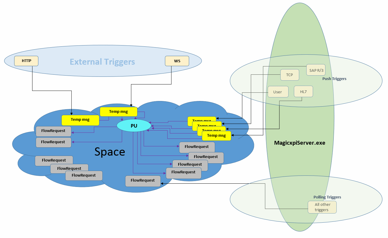
Message Flow – Magic xpi engines communicate with the Space through a GigaSpaces proxy, which is a software module that connects client applications to the Space. Each Magic xpi engine can run flow threads and trigger threads. In addition, there are external triggers running in other process Spaces, such as the HTTP trigger or the Web Services trigger. Triggers create new flow invocation request messages that are handled by workers, either synchronously or asynchronously. The following image shows the trigger architecture in Magic xpi.

External Triggers
Magic xpi can receive a variety of requests:
-
A request for Magic xpi that arrives in the HTTP IIS is handled by the <Magic xpi 4.5>\Runtime\scripts\bin\MgWebRequester.dll file, according to the <Magic xpi 4.5>\Runtime\scripts\config\mgreq.ini file.
-
A request for Magic xpi that arrives in the Apache Tomcat server (Java) is handled by the <Magic xpi 4.5>\Runtime\Support\JavaWebRequester\TomCat\magicxpi4.war file, according to the mgreq.ini file that is defined in the CATALINA_HOME\bin\startup.bat file in the -Dcom.magicsoftware.requester.conf parameter (see the Magic xpi - Java-Based Installation Instructions.pdf).
-
A request for Magic xpi that arrives in the Systinet server (WS server) is handled by the <SSJ for Magic xpi>\lib\MgRequester.jar file, according to the mgreq.ini file that is defined in the <SSJ for Magic xpi>\bin\server.bat file in the -Dcom.magicsoftware.requester.conf parameter.
All of these then put a Temp msg (shown in yellow in the above image) into the Space.
|
Note:
|
Each trigger type has its own Temp msg type, which can be seen in the GigaSpaces UI. In this image, Temp msg was used for all triggers for the purpose of explaining the architecture.
|
Push Triggers
A request for Magic xpi that arrives from push triggers is handled by (the Mgrequest class in) the <Magic xpi 4.5>\Runtime\java\lib\uniRequester.jar file inside the Magic xpi server process (no mgreq.ini file is involved), which puts a Temp msg into the Space. This is different from WS/HTTP, which handles the request in a separate process.
Polling Triggers
All other requests that invoke a trigger are handled inside the Magic xpi server process (no mgreq.ini file is involved) which directly writes FlowRequest messages to the Space.
Available workers in the MagicxpiServer.exe file take FlowRequest messages and execute them, taking into account the project’s constraints (max instances, licenses, and so on).
* User Requests = mgrqcmdl, CallRemote
Processing Units (PUs)
There are two dedicated PUs (one PU for the HTTP trigger type, named http2ifr, and one PU for all others, named externalRequestToFlowRequest*) in the Space that convert these Temp msgs into FlowRequest messages. These FlowRequest messages are handled by the MagicxpiServer.exe file, and can be seen in the Monitor and in the GigaSpaces UI (the data type name is com.magicsoftware.xpi.server.messages.FlowRequest).
* The http2ifr and externalRequestToFlowRequest PUs can be seen in the Event Containers section of the GigaSpaces UI.
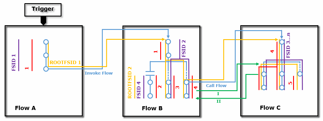
A thorough understanding of the server architecture is very useful when defining a project’s recovery settings. The following diagram shows how the server architecture works.

|
ROOTFSID 1
|
The Root Flow Sequence ID (Root FSID) is the same for all flows and branches within the same runtime tree.
|
|
ROOTFSID 4
|
A stand-alone branch starting a new runtime tree.
|
|
ROOTFSID #
|
The number is the same as the initial FSID’s number.
|
|
FSID
|
Each new flow receives a new Flow Sequence ID (FSID). A stand-alone branch is considered a separate flow, so it gets a new FSID of its own.
|
|
1...5 = Flow Request ID
|
Each triggered flow, parallel branch, or stand-alone branch is invoked by a flow request message, which has its own ID. "Invoke flow" step and "call flow" destinations are part of a linear execution, and therefore do not have their own flow request messages.
|
|
I, II
|
For each call flow iteration, the called flow (I) is assigned a new FSID. When the called flow returns to the calling flow (II), the calling flow (II) remains with its original FSID.
|

